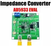
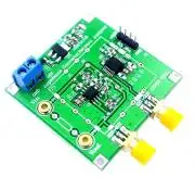
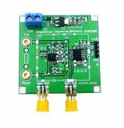
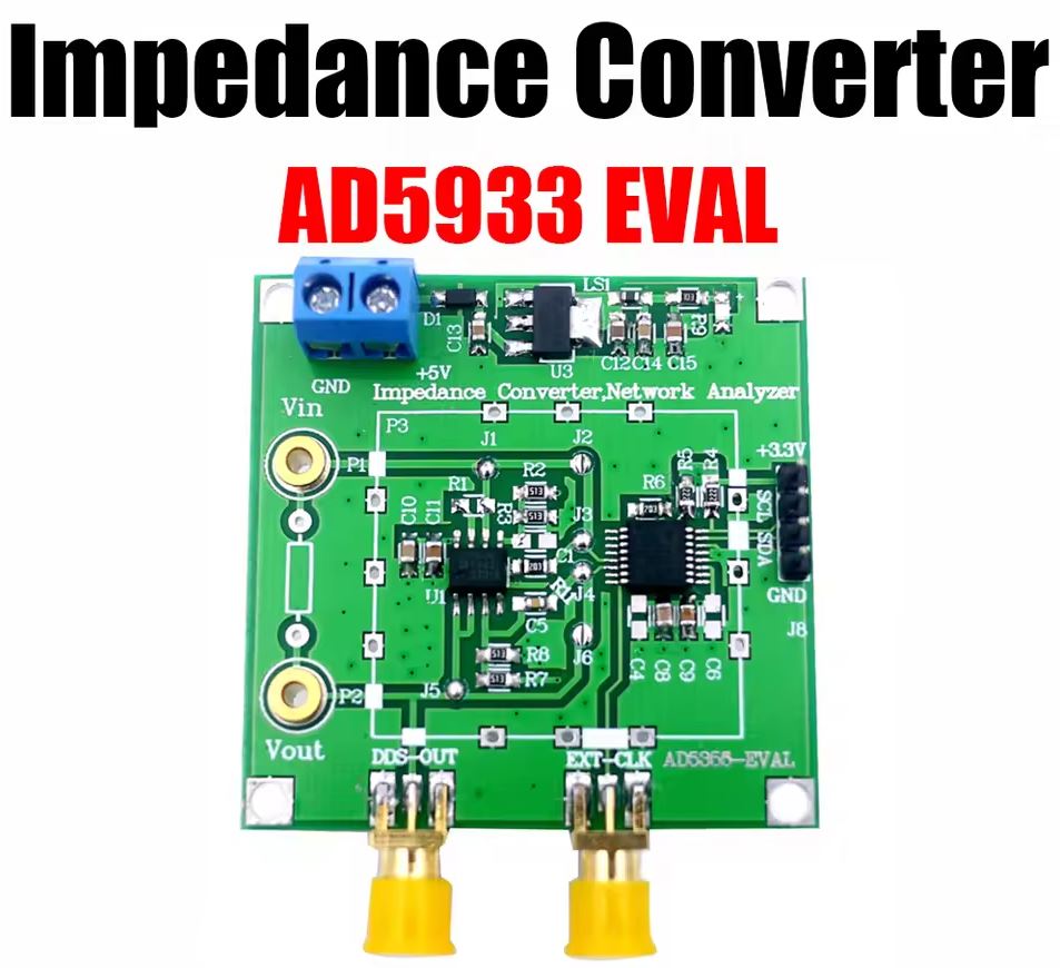
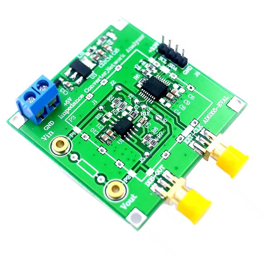
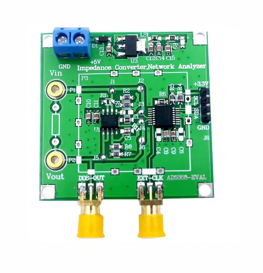
AD5933 alapú 12-bites impedancia konverter és hálózat analizátor modul
AD5933-M
- Tápfeszültség: 2.7...5.5V DC
- Interface: I2C
- I2C cím: 0x1A
- Frekvencia tartomány : programozható, akár 100kHz
- Frekvencia felbontás: 27 bites (<0,1 Hz)
- Impedancia mérési tartomány: 1 kΩ-tól 10 MΩ-ig
(Kiegészítő áramkörökkel 100 Ω és 1 kΩ)
- Belső hőmérséklet-érzékelő (±2°C)
- Belső rendszeróra opció
- Fázismérési képesség
- 0,5%-os rendszerpontosság
- Hőmérséklettartomány: −40...125°C
Alkalmazás:
- Elektrokémiai analízis
- Bioelektromos impedancia analízis
- Impedancia spektroszkópia
- Komplex impedancia mérés
- Korróziófigyelő és védő berendezések
- Biomedicinális és autóipari érzékelők
- Közelségérzékelés
- Roncsolásmentes vizsgálat
- Anyagtulajdonság-elemzés
- Üzemanyag-/akkumulátorcellák állapotának monitorozása
Mód konfiguráció:
- Közvetlen mód: Összekötve: J2, J6, Szakadás: J1, J3, J4, J5
-Kettős műveleti erősítő mód: Összekötve: J1, J3, J4, J5, Szakadás: J2, J6
Mode configuration:
AD5933 Impedance Converter Network analyzer module 1M sampling rate 12bit resolution measurement resistance
Product Application:
-Electrochemical analysis
-Bioelectrical impedance analysis
-Impedance spectrum analysis
-Complex impedance measurement
-Corrosion monitoring and protection equipment
-Biomedical and Automotive Sensors
-Bioelectrical impedance analysis
-Proximity sensing
-Non destructive testing
-Material Property Analysis
-Fuel/Cell Status Monitoring
Sample Prorgam:
#include "sys.h"
#include "ad5933.h"
#include "delay.h"
#include <math.h>
#define AD5933_ADDRESS 0x1A // Define AD5933 slave address, its default serial bus address is
// 0001101(0x0D), but since the slave address high seven bits are the device address
// (0x0D), the actual slave address is the device address shifted left by one bit
// i.e. (0x1A)
#define POINTER_COMMAND 0xB0 // Define pointer setting command (10110000)
#define Gain_factor 5.0725e-9
#define PI 3.1415926536
#define System_Phase 109.052767
#define rad_to_degree 180 / PI
double
GainFactor[] = {5.1143e-9, 5.1146e-9, 5.1162e-9, 5.11645e-9,
5.11699e-9, 5.1175e-9, 5.11774e-9, 5.1189e-9, 5.11983e-9, 5.12105e-9};
double SystemPhase[] = {290.994, 291.721, 292.452, 293.168, 293.870, 294.596, 295.336, 296.009, 296.750, 297.492};
int Receive_byte[1]; // Define receive array
short int status_register; // Define status register variable
int Re, Im; // Real part, imaginary part
double Magnitude, Impedance, Phase; // DFT amplitude value, impedance value, phase value
void AD5933_Init(void)
{
delay_ms(100); // This delay is very important
// Transmit to start frequency register
// program 30khz start frequency assuming internal osc of 16.776Khz
i2c_write ( 0x84, 0x45);
i2c_write ( 0x83, 0xA6);
i2c_write ( 0x82, 0x0E);
// Transmit to frequency increment register
// program 1Khz frequency increment assuming internal osc of 16.776Khz
i2c_write ( 0x87, 0x02);
i2c_write ( 0x86, 0x7D);
i2c_write ( 0x85, 0x00);
// Transmit to NUMBER OF INCREMENTS register
// program 10 frequency increments
i2c_write ( 0x89, 0x0A);
i2c_write ( 0x88, 0x00);
// Transmit to settling time cycles register
// program 15 output cycles at each frequency before a adc conversion
i2c_write ( 0x8B, 0x0F);
i2c_write ( 0x8A, 0x00);
// Transmit to CONTROL register
// place the AD5933 in standby mode
i2c_write ( 0x80, 0xB0);
// Choose the internal system clock
i2c_write ( 0x81, 0x00);
// initialise the sensor with contents of start frequency regsister with range 1 (2vp-p, 1.6v) PGA = x1
i2c_write ( 0x80, 0x11);
delay_ms(5); // This delay is to allow the circuit to reach a stable state after sending the initialization command
// start of frequency sweep (2vp-p, 1.6v) PGA = x1
i2c_write ( 0x80, 0x21);
// initialise the sweep sequence
}
void sweep (void)
{
unsigned int real_byte_high;
unsigned int real_byte_low;
unsigned int imag_byte_high;
unsigned int imag_byte_low;
signed short int imag_data;
signed short int real_data;
int m = 0; // Gain factor array and system phase array counter
printf ("Start of Frequency sweep"); // printf function call
delay_ms(10);
for(;;)
// status reg D0 = valid temp, D1 = valid real/imag data, D2 = frequency sweep complete
{
// D1 status reg loop
status_register = AD5933_read(0x8F); // read the status register
status_register = (status_register & 0x2); // mask off the valid data bit
if( ((status_register) 0xFD ) == 0xFF) // valid data should be present after start freqy command
{
//D1 true condition
if( (AD5933_read(0x8F) 0xFB )!= 0xFF) // D2 test condition
{
real_byte_high = AD5933_read(0x94);
real_byte_low = AD5933_read(0x95);
imag_byte_high = AD5933_read(0x96);
imag_byte_low = AD5933_read(0x97);
real_data = ((real_byte_high << 8) real_byte_low);
imag_data = ((imag_byte_high << 8) imag_byte_low);
Re = (int) real_data;
Im = (int) imag_data;
Magnitude = sqrt(pow(Re,2) + pow(Im,2));
Impedance = 1/(Magnitude * GainFactor[m]);
if(Re>0 && Im>0)
Phase = (atan((double)Im / (double)Re) * rad_to_degree) - SystemPhase[m];
else if(Re>0 && Im<0)
Phase = (360+ atan((double)Im / (double)Re) * rad_to_degree) - SystemPhase[m];
else
Phase = (180+ atan((double)Im / (double)Re) * rad_to_degree) - SystemPhase[m];
printf ("The Impedance is %f ohm", Impedance);
delay_ms(10);
printf ("The Phase is %f degree", Phase);
delay_ms(10);
m++;
i2c_write ( 0x80, 0x31); // increment to the next frequency
} // end of D2 test condition
else // End of frequency sweep exit loop
{
break;
}
} // end of D1 true condition
} // end of for loop
}// end of sweep function
Kapcsolódó termékek
Kapcsolódó cikkek
Vélemények (küldje be Ön is véleményét)
Cégünk elektronikai és szoftveres fejlesztésekkel foglalkozik, ami mellett internetes kereskedelmet is indítottunk az ehhez kapcsolódó modulok és fejlesztő egységekkel. Már több mint 15.000 féle termék rendelhető, melyből több mint 5000 saját raktárunkról azonnal elérhető. Fiatal cégként dinamikusan bővülünk, alkalmazkodunk a modern igényekhez. Támogatjuk a hazai fejlesztéseket, és diákokat, termékekkel, szolgáltatásokkal, és saját tudásunkkal. Rendszeres vásárlóink között tudhatunk rengeteg magyar nagyvállalatot, oktatási intézményt, megbízóink között pedig több fejlődő kis- és közép- vállalkozást.
2016-tól mi béreljük az elektrobot.hu-t, mely egy közösségi blog és híroldalként indult, ezen keresztül korábban több elektronikai cég forgalmazott, és jelenleg is hírdeti szolgáltatásait. Rendszeresen jelen vagyunk a magyar elektronikai fórumokon online és kiállítások, rendezvények formájában. Próbáljuk összehozni az oktatásban és versenyeken résztvevőket a fiatal cégekkel, és a komolyabb megbízókkal.


