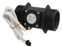
Az YF-B7 változat beépített hőmérséklet szenzorral van ellátva, mely egy 50kOhm-os NTC szenzor.
Hossza: ~66mm
Menetek hossza a két oldalon: 16mm a hosszabb, és 10.5mm a rövidebb oldalon
Általános Arduin Tutorial víz átfolyás szenzorokhoz: How to Use Water Flow Sensor - Arduino Tutorial
Water flow sensor:
2 water pressure> 1.75MPa
3 Operating voltage range DC5 ~ 15V (abs max 5-18V)
4 Insulation resistance> 100MΩ
5 Accuracy (in 1 ~ 25L \ MIN) ± 3%
6 Flow Pulse Characteristics (11 * Q) Q = L / Min ± 3%
7 Output pulse high> DC 4.7V (input voltage DC 5V)
8 Output pulse low level
- Temperature sensor:
- Type: NTC
- Resistance: 50KΩ
- Beta value: 3950
- Connector: JST-SM 2p female
- Thread: M8
YF-B1 Hall Effect Water Flow Meter / Sensor
This sensor sits in line with your water line and contains a pinwheel sensor to measure how much liquid has moved through it. There's an integrated magnetic hall effect sensor that outputs an electrical pulse with every revolution. The hall effect sensor is sealed from the water pipe and allows the sensor to stay safe and dry.
The sensor comes with three wires: red (5-15VDC power), black (ground) and yellow (Hall effect pulse output). By counting the pulses from the output of the sensor, you can easily calculate water flow. Note this isn't a precision sensor, and the pulse rate does vary a bit depending on the flow rate, fluid pressure and sensor orientation. It will need careful calibration if better than 10% precision is required. However, its great for basic measurement tasks!
We have as example Arduino sketch that can be used to quickly test the sensor, it will calculate the approximate flow of water in liters/hour.
The pulse signal is a simple square wave so its quite easy to log and convert into liters per minute using the following formula.
Pulse frequency (Hz) / 11 = flow rate in L/min.
Specification
- Mini. Wokring Voltage: DC 4.5V
- Max. Working Current: 15mA (DC 5V)
- Working Voltage: 5V~24V
- Flow Rate Range: 1~25L/min
- Load Capacity: ≤10mA(DC 5V)
- Operating Temperature: ≤80℃
- Liquid Temperature: ≤120℃
- Operating Humidity: 35%~90%RH
- Water Pressure: ≤1.75MPa
- Storage Temperature: -25℃~+80℃
- Storage Humidity: 25%~95%RH
Materials
- Body: copper brass
- Stainless steel bead: Stainless steel SUS304
- Axis: Stainless steel SUS304
- Impeller: POM
- Magnet: Ferrite
- Cover: PA66
- Screw: 4 Stainless steel SUS304 3.0*11
- Cable: 1007 24AWG
Reading Water Flow rate with Water Flow Sensor
This is part of a project I have been working on and I thought I would share it here since there have been a few threads on how to read water flow rate in liters per hour using the Water Flow Sensor found in the Seeed Studio Depo. It uses a simple rotating wheel that pulses a hall effect sensor. By reading these pulses and implementing a little math, we can read the liquids flow rate accurate to within 3%.
Wiring Diagram
The external diameter of thread the connections use is 1.4mm.
Output Table
- Pulse frequency (Hz) in Horizontal Test: = 11Q, Q is flow rate in L/min. (Results in +/- 3% range)
- Output pulse high level Signal voltage: >4.5 V (input DC 5 V)
- Output pulse low level Signal voltage: <0.5V (input DC 5V)
- Precision: 3% (Flow rate from 1L/min to 10L/min)
- Output signal duty cycle: 40%~60%
Kapcsolódó termékek
Kapcsolódó cikkek
Vélemények (küldje be Ön is véleményét)
Cégünk elektronikai és szoftveres fejlesztésekkel foglalkozik, ami mellett internetes kereskedelmet is indítottunk az ehhez kapcsolódó modulok és fejlesztő egységekkel. Már több mint 15.000 féle termék rendelhető, melyből több mint 5000 saját raktárunkról azonnal elérhető. Fiatal cégként dinamikusan bővülünk, alkalmazkodunk a modern igényekhez. Támogatjuk a hazai fejlesztéseket, és diákokat, termékekkel, szolgáltatásokkal, és saját tudásunkkal. Rendszeres vásárlóink között tudhatunk rengeteg magyar nagyvállalatot, oktatási intézményt, megbízóink között pedig több fejlődő kis- és közép- vállalkozást.
2016-tól mi béreljük az elektrobot.hu-t, mely egy közösségi blog és híroldalként indult, ezen keresztül korábban több elektronikai cég forgalmazott, és jelenleg is hírdeti szolgáltatásait. Rendszeresen jelen vagyunk a magyar elektronikai fórumokon online és kiállítások, rendezvények formájában. Próbáljuk összehozni az oktatásban és versenyeken résztvevőket a fiatal cégekkel, és a komolyabb megbízókkal.


